

By Rajendra prasad
What are industrial fans(IF) and blowers?
Industrial fans and blowers are machines whose primary function is to provide and accommodate a large flow of air or gas to various parts of a building or other structures. This is achieved by rotating a number of blades, connected to a hub and shaft, and driven by a motor or turbine. The flow rates of these mechanical fans range from approximately 200 cubic feet (5.7 m3) to 2,000,000 cubic feet (57,000 m3) per minute. A blower is another name for a fan that operates where the resistance to the flow is primarily on the downstream side of the fan.
What are the Functions and Applications of IFs?
There are many uses for the continuous flow of air or gas that industrial fans generate, including combustion, ventilation, aeration, particulate transport, exhaust, cooling, air-cleaning, and drying, to name a few. The industries served include electrical power production, pollution control, metal manufacturing and processing, cement production, mining, petrochemical, food processing, cryogenics, and clean rooms.
“The industries served include electrical power production, pollution control, metal manufacturing and processing, cement production, mining, petrochemical, food processing, cryogenics, and clean rooms.”
Is there further classisfication in Industrial fans?
Most industrial fans may be categorized into one of two general types: centrifugal fans and axial fans.
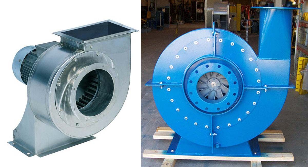
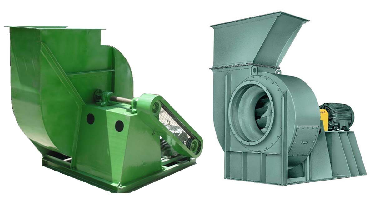
Centrifugal
The centrifugal design uses the centrifugal force generated by a rotating disk, with blades mounted at right angles to the disk, to impart movement to the air or gas and increase its pressure. The assembly of the hub, disk and blades is known as the fan wheel, and often includes other components with aerodynamic or structural functions. The centrifugal fan wheel is typically contained within a scroll-shaped fan housing, resembling the shell of the nautilus sea creature with a central hole. The air or gas inside the spinning fan is thrown off the outside of the wheel, to an outlet at the housing’s largest diameter. This simultaneously draws more air or gas into the wheel through the central hole. Inlet and outlet ducting are often attached to the fan’s housing, to supply and/or exhaust the air or gas to the industry’s requirements.
There are many varieties of centrifugal fans, which may have fan wheels that range from less than 3 cm to over 16 feet (5 m) in diameter.
Axial
The axial design uses axial forces to achieve the movement of the air or gas, spinning a central hub with blades extending radially from its outer diameter. The fluid is moved parallel to the fan wheel’s shaft, or axis of rotation. The axial fan wheel is often contained within a short section of cylindrical ductwork, to which inlet and outlet ducting can be connected.
Axial fan types have fan wheels with diameters that usually range from less than a foot (0.3 meters) to over 30 feet (9 m), although axial cooling tower fan wheels may exceed 82 feet (25 m) in diameter.
In general, axial fans are used where the principal requirement is for a large volume of flow, and the centrifugal design where both flow and higher pressures are required.
What are the variable parameters?
There are several means of controlling the flow rate of a fan, e.g., temporarily reducing the air or gas flow rate; these can be applied to both centrifugal and axial fans.
Speed Variation – All of the fan types described above can be used in conjunction with a variable speed driver. This might be an adjustable frequency AC controller, a DC motor and drive, a steam turbine driver, or a hydraulic variable speed drive unit (“fluid drive”). Flow control by means of variable speed is typically smoother and more efficient than by means of damper control. Significant power savings (with reduced cost of operation) are possible if variable speed fan drives are used for applications that require reduced flow operation for a significant portion of the system operating life.
Industrial Dampers – These devices also allow fan volumetric flow control during operation, by means of panels so as to direct gas flow or restrict the inlet or outlet areas.
There is a variety of dampers available:
Louvered Inlet Box Dampers
Radial Inlet Dampers
Variable Inlet Vane (VIV) Dampers
Vortex Dampers
Discharge Dampers